Casual Info About How Do You Average A PWM Signal

How To Make Pwm Signal A 14v 12v
Understanding PWM Signals
1. What exactly is a PWM signal, anyway?
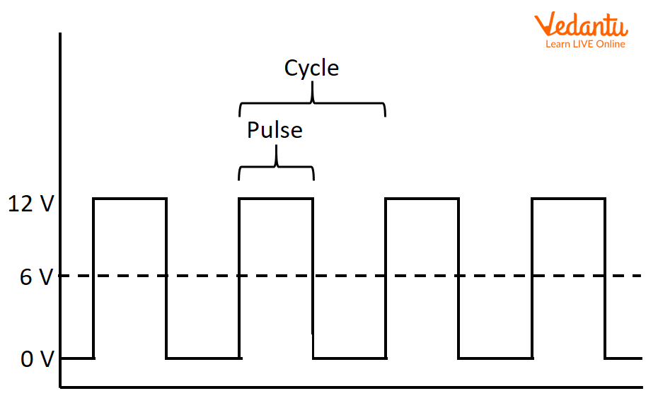
Okay, let's say you're trying to dim a light bulb. The simple way? A dimmer switch, right? A Pulse Width Modulation (PWM) signal is kind of like a super-fast, electronic dimmer switch. Instead of physically turning a knob, we're rapidly switching a signal on and off. The proportion of time it's "on" versus "off" within a given cycle determines the effective voltage delivered. Think of it as flickering the light really fast; your eyes can't see the flicker, but they perceive the average brightness.
PWM is commonly used in applications where we need to control power to a device without significant energy loss. Motors are a prime example. Imagine trying to control the speed of a toy car's motor just by varying the voltage directly. You'd waste a lot of energy as heat. PWM allows us to control the speed efficiently by switching the power on and off very quickly, controlling the average amount of power delivered to the motor.
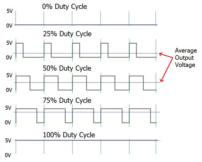
So, the key things to remember about PWM are its "on time" (the pulse width) and its "off time." Together, they make up one cycle. The duty cycle is the percentage of time the signal is "on" during that cycle. A 50% duty cycle means the signal is on half the time and off half the time. A 100% duty cycle means it's always on, and a 0% duty cycle means it's always off. Makes sense, right?
The magic of PWM lies in our ability to control that duty cycle with great precision. By adjusting the duty cycle, we can effectively adjust the average voltage or current delivered to a load. This opens up a world of possibilities for controlling everything from motor speeds and LED brightness to audio volume and servo motor positions. And that's why understanding how to interpret, and thus how to average a PWM signal is important.

Why Average a PWM Signal?
2. The practical side of things
Why even bother averaging a PWM signal? Well, sometimes you don't care about the individual pulses. You just want to know the equivalent DC voltage that the PWM signal represents. Think of a microcontroller that's outputting a PWM signal to control the brightness of an LED. Another part of the system might need to know what brightness level is currently set. It doesn't need to know the PWM waveform itself; it just needs the average voltage.
Averaging a PWM signal also helps in situations where you're dealing with noisy signals. Real-world signals aren't always perfectly clean. Averaging can help smooth out the noise and give you a more stable and reliable reading. It's like taking multiple measurements and averaging them together to get a more accurate result — a common trick used in all sorts of scientific applications.
Beyond monitoring, averaging is also crucial when you're using PWM to control analog devices. Many analog circuits respond to the average voltage they receive. For example, an amplifier might amplify the average level of a PWM signal. To understand how the analog circuit is responding, you need to know the average voltage of the PWM signal.
Imagine you are designing a smart home system and you need to monitor the power consumption of a PWM-controlled device. Instead of constantly tracking the individual pulses of the PWM signal, you can average the signal over a certain period. This gives you a single value representing the average power consumption, which is much easier to work with in your overall power management system. It's all about simplifying complex data into something useful.

How To Measure Pwm Current At Elaine Boehme Blog
Methods for Averaging PWM Signals
3. From simple to sophisticated
There are a few different ways to average a PWM signal, each with its own pros and cons. The simplest way, conceptually, is to use a resistor-capacitor (RC) low-pass filter. This circuit smooths out the PWM signal, letting the low-frequency (average) component pass through while blocking the high-frequency switching component. The values of the resistor and capacitor determine the cutoff frequency of the filter, which needs to be chosen appropriately based on the PWM frequency.
Another method involves using a microcontroller's built-in analog-to-digital converter (ADC). The microcontroller can sample the PWM signal at regular intervals and then calculate the average value over a specified time period. This approach provides more flexibility than the RC filter, as you can adjust the sampling rate and averaging period in software. Plus, you can perform more complex calculations on the data, such as filtering out noise or compensating for non-linearities.
For very precise measurements, you can use a dedicated averaging circuit, such as an integrating amplifier. These circuits are designed to perform accurate averaging over a wide range of frequencies and signal levels. However, they tend to be more complex and expensive than the RC filter or microcontroller-based approach.
The best method for averaging a PWM signal depends on your specific requirements. If you need a simple and inexpensive solution, an RC filter might be sufficient. If you need more flexibility and control, a microcontroller with an ADC is a good choice. And if you need the highest possible accuracy, an integrating amplifier is the way to go. Consider your available resources, accuracy needs, and the nature of your application when making your decision.

Calculating the Average PWM Signal Value
4. The math behind the magic
The theoretical average value of a PWM signal is surprisingly straightforward to calculate. You just need two pieces of information: the peak voltage (or amplitude) of the signal and the duty cycle. The average voltage is simply the peak voltage multiplied by the duty cycle. For example, if you have a 5V PWM signal with a 60% duty cycle, the average voltage is 5V * 0.60 = 3V.
This calculation assumes that the PWM signal is perfectly square, with instantaneous transitions between the on and off states. In reality, PWM signals often have some rise and fall time, which can slightly affect the average value. However, for most applications, this effect is negligible. If you need extremely precise measurements, you can use more sophisticated techniques to compensate for the rise and fall times.
It's important to express the duty cycle as a decimal (between 0 and 1) when performing the calculation. Don't use the percentage directly. A 75% duty cycle should be entered as 0.75. This is a common mistake that can lead to incorrect results.
If you're using a microcontroller to calculate the average value, you can implement this formula directly in your code. Read the duty cycle value (which may come from another sensor or a user input) and multiply it by the known peak voltage of your PWM signal. The resulting value will be the average voltage. Make sure your code handles any potential edge cases, such as a duty cycle outside the 0-1 range.

Practical Applications and Considerations
5. Putting it all together
Let's think about practical applications of averaging PWM signals. Imagine a solar panel charging system. A PWM charge controller uses a PWM signal to regulate the voltage applied to the battery. By averaging the PWM signal, you can accurately monitor the charging voltage and ensure that the battery is being charged safely and efficiently. If the average voltage is too high, the controller can reduce the duty cycle to prevent overcharging. If it's too low, the controller can increase the duty cycle to maximize charging efficiency.
In audio amplifiers, PWM is sometimes used to generate high-efficiency Class-D amplifiers. The audio signal is encoded as a PWM signal, which is then amplified by a switching amplifier. Averaging the PWM signal allows you to reconstruct the original audio signal, which can then be fed to a speaker. The averaging process is typically performed by a low-pass filter, which removes the high-frequency switching components and leaves only the audio signal.
When working with PWM signals, it's important to consider the switching frequency. Higher switching frequencies generally result in smoother waveforms, but they can also increase electromagnetic interference (EMI). Lower switching frequencies can reduce EMI, but they might also introduce more ripple in the averaged signal. Choose the switching frequency carefully based on your application requirements.
Finally, remember that the accuracy of your averaging method depends on the quality of your components and the precision of your measurements. Use high-quality resistors and capacitors in your RC filters, and calibrate your ADCs regularly. Pay attention to noise and interference in your system, and take steps to minimize it. With careful design and implementation, you can achieve accurate and reliable averaging of PWM signals in a wide range of applications.
